Building a Keyboard with tscircuit
Overview
This tutorial guides you through creating a custom mechanical keyboard PCB using tscircuit. We'll cover setting up your environment, understanding the core components, building a key matrix, creating a simple 4-key keyboard, and finally scaling up to a standard 60% layout using data from Keyboard Layout Editor.
We'll be using a Raspberry Pi Pico as the microcontroller, Kailh Choc-style key switches, and standard diodes for the matrix.
1. Set Up Your Environment
Before we start building, let's get your development environment ready.
Prerequisites
You need Node.js or Bun installed on your system.
Install tscircuit CLI
Install the tscircuit command-line interface (CLI) globally using npm or bun:
npm install -g @tscircuit/cli
# or
bun install -g @tscircuit/cli
This installs the tsci command, which you can use to create, develop, and export tscircuit projects.
Create a New Project
Navigate to where you want to create your project and run tsci init:
mkdir my-keyboard
cd my-keyboard
tsci init
This command bootstraps a new tscircuit project with a basic structure, including an index.tsx file (our main circuit definition), package.json, tsconfig.json, and other necessary configuration files.
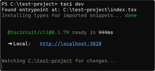
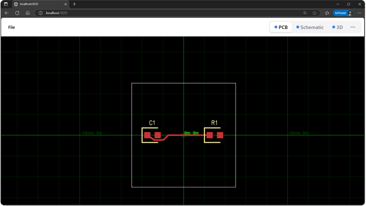
Run the Development Server
Start the tscircuit development server by running:
tsci dev
This command compiles your index.tsx file and serves it on http://localhost:3020 (or the next available port). Open this URL in your browser. You should see a live preview of your circuit, including PCB, Schematic, and 3D views. The server watches for file changes and automatically updates the preview.
2. Import the Main Components
A keyboard PCB primarily consists of three types of components:
- Microcontroller: The "brain" that scans the keys and communicates with the computer. We'll use a Raspberry Pi Pico.
- Key Switches: The physical buttons you press. We'll use a generic Kailh Choc footprint component.
- Diodes: Prevent "ghosting" (incorrect key press readings) in the matrix.
Let's import these into our project.
First, you'll need to install the packages containing the Pico and Key components:
tsci add @tsci/seveibar.PICO @tsci/seveibar.Key
Now, let's import and preview each component to see what we're working with:
Microcontroller (Raspberry Pi Pico)
We import the PICO component. It provides the necessary footprint and pin definitions for the Raspberry Pi Pico.
import { PICO } from "@tsci/seveibar.PICO";

export default () => (
<board width="50mm" height="60mm">
  <PICO name="U1" />
</board>
);
Hot-Swappable Key Switch (Kailh Choc Style)
We import a Key component, representing a single switch with its footprint. This
component is comprised of a couple different footprints and 3d models, but when
placed on the board is just a small plastic piece that key switches can be
pressed into.
import { Key } from "@tsci/seveibar.Key";

export default () => (
<board width="30mm" height="30mm">
  <Key name="K1" />
</board>
);
Diode (1N4148WS SMD)
Let's import a diode component. The 1N4148WS is one of the most in-stock and common
diodes according to jlcsearch. We
can use the File > Import menu to quickly add it to our project. You should get
something like this:
import type { ChipProps } from "@tscircuit/props"

const pinLabels = {
  pin1: ["C"], // Cathode
  pin2: ["A"], // Anode
} as const

export const A_1N4148WS = (props: ChipProps<typeof pinLabels>) => {
  return (
    <chip
      pinLabels={pinLabels}
      symbolName="diode"
      supplierPartNumbers={{
        jlcpcb: ["C57759"],
      }}
      manufacturerPartNumber="A_1N4148WS"
      footprint={
        <footprint>
          <smtpad
            portHints={["pin1"]} // Cathode
            pcbX="-1.1725910000000113mm"
            pcbY="0mm"
            width="0.9999979999999999mm"
            height="0.7500112mm"
            shape="rect"
          />
          <smtpad
            portHints={["pin2"]} // Anode
            pcbX="1.1725910000000113mm"
            pcbY="0mm"
            width="0.9999979999999999mm"
            height="0.7500112mm"
            shape="rect"
          />
          {/* Silkscreen omitted for brevity */}
        </footprint>
      }
      cadModel={{
        objUrl:
          "https://modelcdn.tscircuit.com/easyeda_models/download?uuid=973acf8a660c48b1975f1ba1c890421a&pn=C57759",
        rotationOffset: { x: 0, y: 0, z: 0 },
        positionOffset: { x: 0, y: 0, z: 0 },
      }}
      {...props}
    />
  )
}
import { A_1N4148WS } from "./imports/A1N4148WS";

export default () => (
<board width="20mm" height="20mm">
  <A_1N4148WS name="D1" />
</board>
);
3. Create the KeyMatrix Component
Connecting each key switch directly to the microcontroller would require a large number of pins, especially for full-size keyboards. Instead, keyboards use a matrix scanning technique.
How Matrix Scanning Works
- Grid Layout: Keys are arranged logically in a grid of rows and columns.
- Connections: Each key switch connects a specific row wire to a specific column wire when pressed.
- Scanning: The microcontroller activates one row (or column) at a time and checks which columns (or rows) become active. This identifies the pressed key(s) at the intersection.
- Diodes: A diode is placed in series with each switch. This prevents "ghosting," where pressing multiple keys simultaneously might falsely register additional key presses. The diode ensures current flows only in one direction (typically from column to row, or vice-versa depending on the scanning direction).
The KeyMatrix Component
Let's create a reusable React component, KeyMatrix, that takes a keyboard layout definition and pin mappings, then generates the grid of keys and diodes.
We'll need helper functions to parse the layout data (from Keyboard Layout Editor format) and generate reference designators for each key.
First, the helper to generate reference designators based on key labels:
const refDesMap = {
  "~": "K_TILDE",
  "~`": "K_TILDE",
  "!": "K_EXCLAMATION",
  "@": "K_AT",
  "#": "K_HASH",
  $: "K_DOLLAR",
  "%": "K_PERCENT",
  "^": "K_CARET",
  "&": "K_AMPERSAND",
  "*": "K_ASTERISK",
  "(": "K_LPAREN",
  ")": "K_RPAREN",
  "{": "K_LBRACE",
  "}": "K_RBRACE",
  "|": "K_PIPE",
  "[": "K_LSQBRAK",
  "]": "K_RSQBRAK",
  '"': "K_QUOTE",
  "'": "K_SINGLEQUOTE",
  "<": "K_LT",
  ">": "K_GT",
  "?": "K_QUESTION",
  "/": "K_SLASH",
  windows: "K_WINDOWS",
  win: "K_WINDOWS",
  menu: "K_MENU",
  "caps lock": "K_CAPSLOCK",
  ":": "K_COLON",
  ";": "K_SEMICOLON",
  "1": "K_N1",
  "2": "K_N2",
  "3": "K_N3",
  "4": "K_N4",
  "5": "K_N5",
  "6": "K_N6",
  "7": "K_N7",
  "8": "K_N8",
  "9": "K_N9",
  "0": "K_N0",
  "-": "K_MINUS",
  "+": "K_PLUS",
  backspace: "K_BACKSPACE",
  tab: "K_TAB",
  " ": "K_SPACE",
  enter: "K_ENTER",
  shift: "K_SHIFT",
  ctrl: "K_CTRL",
  alt: "K_ALT",
  escape: "K_ESCAPE",
  arrowleft: "K_ARROW_LEFT",
  arrowright: "K_ARROW_RIGHT",
  arrowup: "K_ARROW_UP",
  arrowdown: "K_ARROW_DOWN",
  backquote: "K_BACKQUOTE",
  quote: "K_QUOTE",
  semicolon: "K_SEMICOLON",
  comma: "K_COMMA",
  period: "K_PERIOD",
  slash: "K_SLASH",
  backslash: "K_BACKSLASH",
  bracketleft: "K_BRACKET_LEFT",
  bracketright: "K_BRACKET_RIGHT",
  a: "K_A",
  b: "K_B",
  c: "K_C",
  d: "K_D",
  e: "K_E",
  f: "K_F",
  g: "K_G",
  h: "K_H",
  i: "K_I",
  j: "K_J",
  k: "K_K",
  l: "K_L",
  m: "K_M",
  n: "K_N",
  o: "K_O",
  p: "K_P",
  q: "K_Q",
  r: "K_R",
  s: "K_S",
  t: "K_T",
  u: "K_U",
  v: "K_V",
  w: "K_W",
  x: "K_X",
  y: "K_Y",
  z: "K_Z",
}
export const getRefDesForKey = (key: string): string => {
  const normKeyLabels = key.toLowerCase().split("\n")
  for (const normKeyLabel of normKeyLabels) {
    if (normKeyLabel in refDesMap) {
      return refDesMap[normKeyLabel as keyof typeof refDesMap]
    }
  }
  if (key === "") {
    return "K_SPACE"
  }
  if (key.match(/^[a-zA-Z0-9]+$/)) {
    return `K_${key.toUpperCase()}`
  }
  throw new Error(`No defined refDes for key "${key}"`)
}
Next, the layout parser:
import { getRefDesForKey } from "./getRefDesForKey"; // Corrected import path

export type KLEKey =
  | string
  | {
      x?: number
      y?: number
      w?: number
      h?: number
      x2?: number
      y2?: number
      w2?: number
      h2?: number
      r?: number
      rx?: number
      ry?: number
      n?: boolean
      l?: boolean
      d?: boolean
      g?: boolean
      sm?: string
      sb?: string
      st?: string
      a?: number
    }

export type KLELayout = KLEKey[][]

export const parseKLELayout = (layout: KLELayout) => {
  const KEY_SIZE = 19.05 // Standard keycap size (19.05mm or 0.75 inches)
  const keys: Array<{
    name: string
    x: number
    y: number
    width: number
    height: number
    rotation: number
    rotationX: number
    rotationY: number
    row: number
    col: number
  }> = []

  let currentX = 0
  let currentY = 0
  let currentRotation = 0
  let currentRotationX = 0
  let currentRotationY = 0

  // Default properties for keys
  let currentProps = {
    width: 1,
    height: 1,
    x: 0,
    y: 0,
    align: undefined as undefined | number,
  }

  const nameCounters = new Map<string, number>()
  layout.forEach((row, rowIndex) => {
    currentX = 0
    let colIndex = 0

    row.forEach((item) => {
      if (typeof item === "object") {
        if (item.x !== undefined) currentX += item.x
        if (item.y !== undefined) currentY += item.y
        if (item.w !== undefined) currentProps.width = item.w
        if (item.h !== undefined) currentProps.height = item.h
        if (item.r !== undefined) currentRotation = item.r
        if (item.rx !== undefined) currentRotationX = item.rx
        if (item.ry !== undefined) currentRotationY = item.ry
        if (item.a !== undefined) currentProps.align = item.a
      } else if (typeof item === "string") {
        let refDes = getRefDesForKey(item);
        const baseRefDes = refDes; // Store original refDes before appending counter

        if (nameCounters.has(baseRefDes)) {
          const count = nameCounters.get(baseRefDes)!;
          // If the original key exists and doesn't have a counter suffix, update it
          const ogKey = keys.find((k) => k.name === baseRefDes);
          if (ogKey && !ogKey.name.match(/\d+$/)) {
             ogKey.name = `${baseRefDes}1`; // Assuming first one becomes '1'
          }

          // Increment counter and set new refDes
          nameCounters.set(baseRefDes, count + 1);
          refDes = `${baseRefDes}${count + 1}`;
        } else {
          nameCounters.set(baseRefDes, 1);
          // Don't append '1' if it's the first instance, unless needed later
        }


        keys.push({
          name: refDes,
          x: (currentX + currentProps.width / 2) * KEY_SIZE,
          y: -(currentY + currentProps.height / 2) * KEY_SIZE, // Invert Y for PCB coordinates
          width: currentProps.width * KEY_SIZE,
          height: currentProps.height * KEY_SIZE,
          rotation: currentRotation,
          rotationX: currentRotationX * KEY_SIZE,
          rotationY: currentRotationY * KEY_SIZE,
          row: rowIndex,
          col: colIndex,
        })

        currentX += currentProps.width
        colIndex++

        currentProps.width = 1
        currentProps.height = 1
      }
    })
    currentY++
  })

  // Final pass to ensure keys with the same base name have counters if needed
  const finalNameCounts = new Map<string, number>();
  keys.forEach(key => {
    const baseNameMatch = key.name.match(/^([A-Z_]+)/);
    if (baseNameMatch) {
        const baseName = baseNameMatch[1];
        finalNameCounts.set(baseName, (finalNameCounts.get(baseName) || 0) + 1);
    }
  });

  keys.forEach(key => {
     const baseNameMatch = key.name.match(/^([A-Z_]+)(\d*)$/);
     if (baseNameMatch) {
         const baseName = baseNameMatch[1];
         const numSuffix = baseNameMatch[2];
         if (finalNameCounts.get(baseName)! > 1 && numSuffix === "") {
             // If there are multiple keys with this base name, and this one doesn't have a suffix,
             // assume it's the first one and add '1'. This relies on the initial pass logic.
             // A more robust solution might require re-numbering all duplicates.
             // For simplicity, we'll stick to the logic inferred from the provided code.
             // The original code seems to handle this by potentially renaming the *first*
             // instance when a *second* one is encountered. Let's replicate that nuance.
             // The provided code snippet's name counting logic was slightly ambiguous
             // on exactly *when* the first item gets renamed. Assuming it happens
             // when the second is added.
         }
     }
  });


  return keys
}
Finally, the KeyMatrix component itself:
import { Key } from "@tsci/seveibar.Key";
import { parseKLELayout, type KLELayout } from "./KLELayout"; // Corrected import path
import { A_1N4148WS } from "../imports/A1N4148WS"; // Corrected import path

interface KeyMatrixProps {
  layout: KLELayout
  rowToMicroPin?: string[] // Array mapping row index to net name (e.g., "net.ROW0")
  colToMicroPin?: string[] // Array mapping col index to net name (e.g., "net.COL0")
  name?: string
  pcbX?: number
  pcbY?: number
  schX?: number
  schY?: number
}

export const KeyMatrix = ({
  layout,
  rowToMicroPin,
  colToMicroPin,
  name = "KB",
  pcbX = 0,
  pcbY = 0,
  schX = 0,
  schY = 0,
}: KeyMatrixProps) => {
  const keys = parseKLELayout(layout)

  // Calculate keyboard bounding box to center it
  const minX = Math.min(...keys.map((k) => k.x - k.width / 2))
  const maxX = Math.max(...keys.map((k) => k.x + k.width / 2))
  const minY = Math.min(...keys.map((k) => k.y - k.height / 2))
  const maxY = Math.max(...keys.map((k) => k.y + k.height / 2))
  const centerX = (minX + maxX) / 2;
  const centerY = (minY + maxY) / 2;


  return (
    <group name={name} pcbX={pcbX} pcbY={pcbY} schX={schX} schY={schY}>
      {keys.map((key) => {
        // Calculate the relative position from the center of the keyboard
        const relX = key.x - centerX;
        const relY = key.y - centerY;

        const rowNet = rowToMicroPin?.[key.row];
        const colNet = colToMicroPin?.[key.col];

        // Diode: Anode (A/pin2) -> Key Pin 1, Cathode (C/pin1) -> Row Net
        // Key: Pin 1 -> Diode Anode, Pin 2 -> Column Net

        return (
          <group
            key={key.name}
            // Position the group containing the key and diode
            pcbX={relX}
            pcbY={relY}
            // Adjust schematic positions for better layout
            schX={relX / 10} // Scale down schematic positions
            schY={relY / 10}
          >
            <Key name={key.name} />
            {rowNet !== undefined && (
              <A_1N4148WS
                name={`${key.name}_DIO`}
                connections={{
                  pin2: `.${key.name} .pin1`, // Diode Anode (A) connects to Key pin 1
                  pin1: rowNet,              // Diode Cathode (C) connects to Row net
                }}
                // Position diode relative to the key
                pcbX={0} // Adjust as needed for PCB layout
                pcbY={-7} // Place diode slightly below the key center
                schY={-1} // Place diode below key in schematic
                layer="bottom" // Place diode on the bottom layer
              />
            )}
            {colNet !== undefined && (
              <trace from={`.${key.name} .pin2`} to={colNet} /> // Key pin 2 connects to Col net
            )}
          </group>
        )
      })}
    </group>
  )
}
This component:
- Parses the
layoutusingparseKLELayout. - Calculates the center of the keyboard for relative positioning.
- Iterates through each
keydefinition from the parsed layout. - For each key, it creates a
<group>to hold the key switch and its diode. - Places the
<Key>component. - If
rowToMicroPinis provided for the key's row, it places anA_1N4148WSdiode:- The diode's Anode (A/pin2) connects to the Key's pin1.
- The diode's Cathode (C/pin1) connects to the corresponding row net.
- The diode is placed slightly below the key on the PCB's bottom layer.
- If
colToMicroPinis provided for the key's column, it creates a<trace>connecting the Key's pin2 to the corresponding column net. - Positions the key groups relative to the keyboard's center.
4. Create a Basic 4-Key Keyboard
Now, let's use our KeyMatrix component to create a simple 2x2 keyboard.
We'll define the layout directly in our index.tsx and map the rows/columns to Pico pins.
import { PICO } from "@tsci/seveibar.PICO";
import { KeyMatrix } from "./lib/KeyMatrix"; // Assuming KeyMatrix is in lib/
import type { KLELayout } from "./lib/KLELayout"; // Assuming KLELayout types are in lib/

// Define a simple 2x2 layout
const simpleLayout: KLELayout = [
  ["1", "2"],
  ["3", "4"],
];

// Map rows and columns to Pico pins (using net names for clarity)
const rowPins = ["net.ROW0", "net.ROW1"];
const colPins = ["net.COL0", "net.COL1"];

export default () => (
  <board width="60mm" height="60mm">
    {/* Place the Pico */}
    <PICO
      name="U1"
      pcbX={-25} // Position Pico to the left
      pcbRotation="90deg"
      connections={{
        // Connect Pico pins to our row/column nets
        GP15: rowPins[0], // Row 0
        GP16: rowPins[1], // Row 1
        GP0: colPins[0],  // Col 0
        GP1: colPins[1],  // Col 1
        // Add Ground connections for Pico
        GND1: "net.GND",
        GND2: "net.GND",
        GND3: "net.GND",
        GND4: "net.GND",
        GND5: "net.GND",
        GND6: "net.GND",
        GND7: "net.GND",
      }}
    />

    {/* Place the KeyMatrix */}
    <KeyMatrix
      layout={simpleLayout}
      rowToMicroPin={rowPins}
      colToMicroPin={colPins}
      pcbX={15} // Position matrix to the right
    />
  </board>
);
import { PICO } from "@tsci/seveibar.PICO";
import { KeyMatrix } from "./lib/KeyMatrix"; // Assuming KeyMatrix is in lib/
import type { KLELayout } from "./lib/KLELayout"; // Assuming KLELayout types are in lib/
import { Key } from "@tsci/seveibar.Key"; // Need Key for KeyMatrix
import { A_1N4148WS } from "./imports/A1N4148WS"; // Need Diode for KeyMatrix
import { parseKLELayout } from "./lib/KLELayout"; // Need parser for KeyMatrix
import { getRefDesForKey } from "./lib/getRefDesForKey"; // Need refdes for parser

// Define a simple 2x2 layout
const simpleLayout = [
["1", "2"],
["3", "4"],
];

// Map rows and columns to Pico pins (using net names for clarity)
const rowPins = ["net.ROW0", "net.ROW1"];
const colPins = ["net.COL0", "net.COL1"];

export default () => (
<board width="60mm" height="60mm">
  {/* Place the Pico */}
  <PICO
    name="U1"
    pcbX={-25} // Position Pico to the left
    pcbRotation="90deg"
    connections={{
      // Connect Pico pins to our row/column nets
      GP15: rowPins[0], // Row 0
      GP16: rowPins[1], // Row 1
      GP0: colPins[0],  // Col 0
      GP1: colPins[1],  // Col 1
      // Add Ground connections for Pico
      GND1: "net.GND", GND2: "net.GND", GND3: "net.GND", GND4: "net.GND",
      GND5: "net.GND", GND6: "net.GND", GND7: "net.GND",
    }}
  />

  {/* Place the KeyMatrix */}
  <KeyMatrix
    layout={simpleLayout}
    rowToMicroPin={rowPins}
    colToMicroPin={colPins}
    pcbX={15} // Position matrix to the right
  />
</board>
);
You now have a functional 4-key macropad PCB design!
5. Import a Standard Layout (60% Keyboard)
Manually defining layouts for larger keyboards is tedious. We can use data directly from Keyboard Layout Editor. This website allows you to design layouts graphically and export them as JSON data, which matches our KLELayout type.
Let's use the default60 layout provided in the repomix-output.txt. Create this file:
export const default60 = [
  [
    "~\n`", "!\n1", "@\n2", "#\n3", "$\n4", "%\n5", "^\n6", "&\n7", "*\n8", "(\n9", ")\n0", "_\n-", "+\n=", { w: 2 }, "Backspace",
  ],
  [
    { w: 1.5 }, "Tab", "Q", "W", "E", "R", "T", "Y", "U", "I", "O", "P", "{\n[", "}\n]", { w: 1.5 }, "|\n\\",
  ],
  [
    { w: 1.75 }, "Caps Lock", "A", "S", "D", "F", "G", "H", "J", "K", "L", ":\n;", "\"\n'", { w: 2.25 }, "Enter",
  ],
  [
    { w: 2.25 }, "Shift", "Z", "X", "C", "V", "B", "N", "M", "<\n,", ">\n.", "?\n/", { w: 2.75 }, "Shift",
  ],
  [
    { w: 1.25 }, "Ctrl", { w: 1.25 }, "Win", { w: 1.25 }, "Alt", { a: 7, w: 6.25 }, "", { a: 4, w: 1.25 }, "Alt", { w: 1.25 }, "Win", { w: 1.25 }, "Menu", { w: 1.25 }, "Ctrl",
  ],
];
Now, update index.tsx to use this layout. We also need to expand our rowPins and colPins to match the requirements of a 60% keyboard (typically 5 rows and up to 15 columns). We'll use the pin assignments from the repomix-output.txt index.tsx example.
import { PICO } from "@tsci/seveibar.PICO";
import { KeyMatrix } from "./lib/KeyMatrix";
import type { KLELayout } from "./lib/KLELayout";
import { default60 } from "./keyboard-layouts/default60"; // Import the 60% layout

// Define row and column nets needed for a 60% layout
const rowPins = [
  "net.ROW0", // Note: Pin names adjusted for clarity, map starts from 0
  "net.ROW1",
  "net.ROW2",
  "net.ROW3",
  "net.ROW4",
];
const colPins = [
  "net.COL0", "net.COL1", "net.COL2", "net.COL3", "net.COL4",
  "net.COL5", "net.COL6", "net.COL7", "net.COL8", "net.COL9",
  "net.COL10", "net.COL11", "net.COL12", "net.COL13", "net.COL14",
];


export default () => (
  <board width="300mm" height="120mm"> {/* Increased board size */}
    {/* Place the Pico */}
    <PICO
      name="U1"
      pcbRotation="-90deg" // Rotate Pico for better placement
      pcbX={-130}          // Position Pico far left
      pcbY={0}
      connections={{
        // Map Pico pins to rows (GP15-GP19)
        GP15: rowPins[0], // Row 0
        GP16: rowPins[1], // Row 1
        GP17: rowPins[2], // Row 2
        GP18: rowPins[3], // Row 3
        GP19: rowPins[4], // Row 4
        // Map Pico pins to columns (GP0-GP14)
        GP0: colPins[0], GP1: colPins[1], GP2: colPins[2], GP3: colPins[3], GP4: colPins[4],
        GP5: colPins[5], GP6: colPins[6], GP7: colPins[7], GP8: colPins[8], GP9: colPins[9],
        GP10: colPins[10], GP11: colPins[11], GP12: colPins[12], GP13: colPins[13], GP14: colPins[14],
        // Add Ground connections
        GND1: "net.GND", GND2: "net.GND", GND3: "net.GND", GND4: "net.GND",
        GND5: "net.GND", GND6: "net.GND", GND7: "net.GND",
      }}
    />

    {/* Place the KeyMatrix using the default60 layout */}
    <KeyMatrix
      layout={default60}
      rowToMicroPin={rowPins}
      colToMicroPin={colPins}
      pcbX={0} // Center the keyboard matrix
      pcbY={0}
    />
  </board>
);
import { PICO } from "@tsci/seveibar.PICO";
import { KeyMatrix } from "./lib/KeyMatrix";
import type { KLELayout } from "./lib/KLELayout";
import { default60 } from "./keyboard-layouts/default60";
import { Key } from "@tsci/seveibar.Key"; // Need Key for KeyMatrix
import { A_1N4148WS } from "./imports/A1N4148WS"; // Need Diode for KeyMatrix
import { parseKLELayout } from "./lib/KLELayout"; // Need parser for KeyMatrix
import { getRefDesForKey } from "./lib/getRefDesForKey"; // Need refdes for parser

// Define row and column nets needed for a 60% layout
const rowPins = [ "net.ROW0", "net.ROW1", "net.ROW2", "net.ROW3", "net.ROW4", ];
const colPins = [ "net.COL0", "net.COL1", "net.COL2", "net.COL3", "net.COL4", "net.COL5", "net.COL6", "net.COL7", "net.COL8", "net.COL9", "net.COL10", "net.COL11", "net.COL12", "net.COL13", "net.COL14", ];

export default () => (
<board width="300mm" height="120mm">
  <PICO
    name="U1"
    pcbRotation="-90deg"
    pcbX={-130}
    pcbY={0}
    connections={{
      GP15: rowPins[0], GP16: rowPins[1], GP17: rowPins[2], GP18: rowPins[3], GP19: rowPins[4],
      GP0: colPins[0], GP1: colPins[1], GP2: colPins[2], GP3: colPins[3], GP4: colPins[4],
      GP5: colPins[5], GP6: colPins[6], GP7: colPins[7], GP8: colPins[8], GP9: colPins[9],
      GP10: colPins[10], GP11: colPins[11], GP12: colPins[12], GP13: colPins[13], GP14: colPins[14],
      GND1: "net.GND", GND2: "net.GND", GND3: "net.GND", GND4: "net.GND",
      GND5: "net.GND", GND6: "net.GND", GND7: "net.GND",
    }}
  />
  <KeyMatrix
    layout={default60}
    rowToMicroPin={rowPins}
    colToMicroPin={colPins}
    pcbX={0}
    pcbY={0}
  />
</board>
);
With this setup, you can easily swap default60 with any other KLE layout JSON data to generate different keyboard PCBs!
Next Steps
- Firmware: You'll need firmware (like KMK, QMK, or ZMK) for the Raspberry Pi Pico to scan the matrix and act as a USB keyboard.
- Export: Use
tsci exportor the download button in the web UI to get Gerber files for manufacturing. - Manufacturing: Order your PCB from a manufacturer like JLCPCB or PCBWay. See our guide on Ordering Prototypes.
- Assembly: Solder the components (Pico, diodes, key switches) onto your manufactured PCB.
Happy building!